At Andrews Cooper, we encourage mentorship and sharing our expertise between individuals and teams. Throughout the year, we encourage a culture of ongoing learning and cross-pollination of skills by offering lunch-time training presentations, called “Lunch & Learns.”
During one of these presentations, Aaron Nelson, a Mechanical Engineer and Technical Lead for AC’s Product Development team, shared his insights on how to understand and better use Geometric Dimensioning and Tolerancing (GD&T) to drive successful outcomes with manufacturers and part inspectors.
His presentation is based upon 25+ years of experience designing parts and assemblies. He also worked in southeast Asia as a Supply Quality Engineer which gives him a deeper understanding of the direct impact of his drawings with part manufacturers and inspectors.
When we asked Aaron why he thinks this type of training creates an advantage for our people and clients of AC, he offered:

“To me, the advantage is that AC has a huge depth and breadth of engineering knowledge. It’s kind of like having our own inside consultancy within the company where our most experienced and mature engineers are available to pass down their knowledge. I’m a resource for other engineers who reach out to me for feedback and ways to improve their drawings using GD&T. That’s the whole purpose behind our company Lunch & Learns. We’re helping each other get better at what we do.”
This blog series highlights many key points from Aaron’s thought-provoking presentation. We hope you find something helpful that translates to an even better appreciation of GD&T. Let’s dive in!
Understanding GD&T & Why We Use It
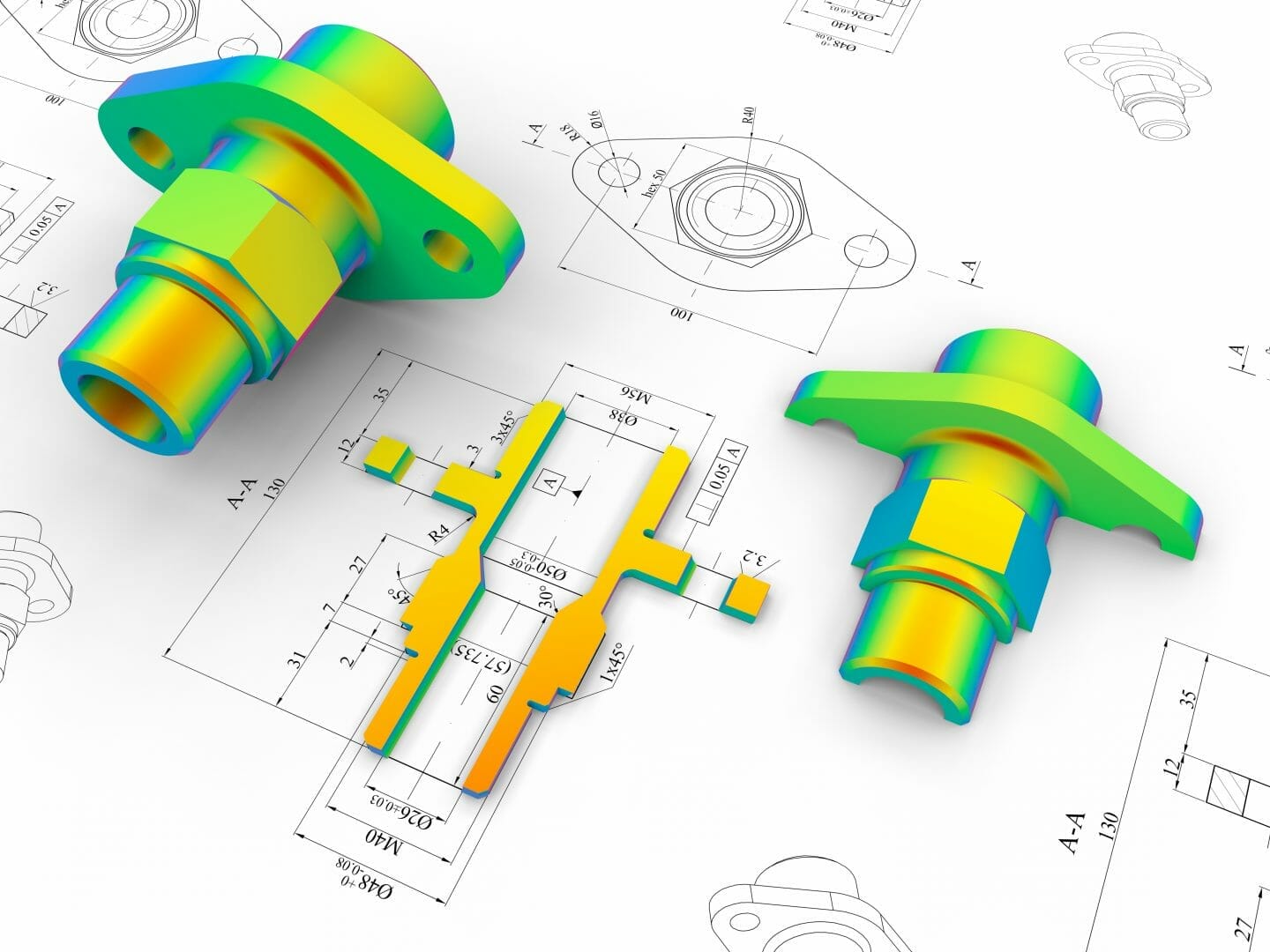
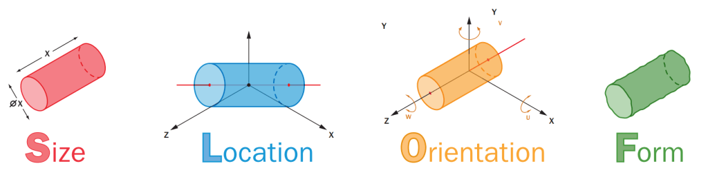
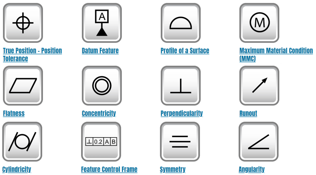
GD&T is a system for designing and defining engineering dimensions and tolerances. Through GD&T, we can clearly define the Size, Location, Orientation, and Form features of our part on the drawing, or SLOF. The GD&T methodology also includes a variety of symbols used to define the specifications of a part’s dimensions and the tolerance limits for its manufacturing.
GD&T Standards
There are two organizations that publish GD&T standards:
> ASME Y14.5 Standard
> ISO GPS Standards
Throughout this article, we are primarily referencing the ASME standard, though we will touch on the special uses of the ISO standard further on in this short series.
Industry Resources
There are also industry resources, like gdandtbasics.com, for further developing our understanding of GD&T symbols and their correct usage within CAD drawings.
“Geometric Dimensioning and Tolerancing is a set of rules and GD&T symbols used on a drawing to communicate the intent of a design, focusing on the function of the part. Using GD&T results in a more accurate design, larger tolerances for less important design features, and cost savings for manufacturing.”
GD&T Basics
Advantages of Improving Our GD&T Skills
As engineers of complex parts, we use GD&T to define dimensions and tolerances in our engineering drawings, but we can also use it to a greater extent to improve part inspection outcomes.
We can think of this process as a discipline that helps guarantee the right outcomes. Similar to the way Design for Manufacturing (DFM) requires us to think about part manufacturing success, with GD&T, we can think of it as “Design for Inspection” (DFI). By taking this approach, we improve our use of GD&T toward the goal of ensuring inspection success. But to do this, we need to understand what GD&T is and who we are communicating with.
The Purpose of GD&T: A language we use to communicate our design intent
At a high level, GD&T is ultimately a form of communication – it’s a language. As with any language, if we fail to communicate clearly, or misunderstand the recipient, it’s likely that the inspection will not go as intended.
From a product engineering perspective, we use GD&T to prevent misunderstandings about the specifications and ensure that our design intent for a part is communicated clearly.
The Audience of GD&T: Not just the inspector, but everyone connected with our part’s design
The type of information we include in our drawings depends on who our audience is and what needs to be understood about our design. We have multiple audiences to consider – we’re not communicating with just one person; we’re conveying important information to everyone who is connected with the part’s design:
> Manufacturer and their team
> Toolers
> Quality Inspectors
> Measuring Technology Operators
> Other Design Engineers and those who come after us
Our drawings need to communicate the unique information needed by each role:
> Design Engineers need to understand the design of the part and how it is to be fixtured and measured.
> Manufacturers and Toolers need to understand how the part is manufactured and interfaces with other parts.
> Quality Inspectors use the same information to inspect the quality of manufactured parts using specific tools, techniques, and fixtures that we can specify in our drawings.
The bottom line: We must apply careful thought and ingenuity in order to communicate the right information in our drawings to the right recipients.
Continued in Part 2: Thinking Outside of CAD for Successful Outcomes