
A device’s functionality is central to a successful product launch. However, other design requirements must perform equally well, such as how an enclosure satisfies an IPX7 waterproofing requirement. It can be easy to forget that just one failure area, like water ingress protection, can render the overall medical device non-compliant.
A single design flaw can incur significant expense, production delay, and redesign efforts to remedy and ensure compliance with industry standards, such as with the ingress protection (IP) code of IEC 60529.
Ideally, with a thorough product development process, this type of failure is identified and adequately vetted well ahead of manufacturing.

One of our customers brought us a challenge to solve a recurring waterproofing reliability issue with their handheld medical device.
Although they had a specification for IPX7 fluid ingress protection, their original design had several manufacturing and field failures. Vacuum leak testing by the manufacturer produced periods of reduced first-pass yield, resulting in excessive rework and scrap costs.
Aware of this recurring leak test failure, we were eager to support them and develop a new design that would consistently meet their IPX7 waterproofing requirement.
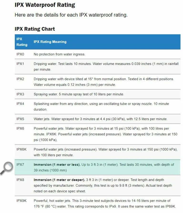
Devices with an IPX7 rating can endure 1-meter water immersion for 30 minutes without harm, making them fully submersible.
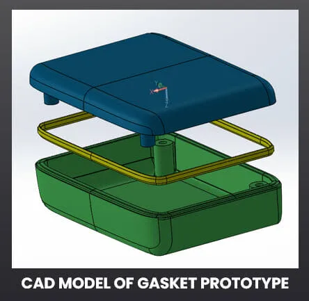
Let's look at several terms to understand the mechanical design of a gasket seal used in this type of waterproof enclosure.
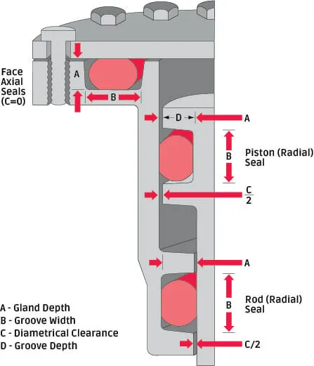
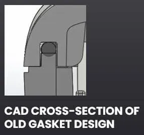
We started our analysis with one of the critical areas for water sealing: the gasket between the front and rear housings.
Our customer's design employed a face seal using a gasket with a round cross-section diameter of 1.2mm. However, the gasket was placed into a groove with a gland depth of 0.9 mm. So, even under perfect conditions, the gasket would be compressed by 0.3mm in the axial direction.
Additionally, because the width of the groove was 1.4mm, it left only 0.1mm of radial clearance on each side of the gasket.
It was clear the existing gasket did not have adequate tolerance to consistently meet the client’s IPX7 waterproofing specification.
Next, as we began our analysis to redesign the gasket, we examined the potential failure modes to identify how the existing face seal design could fail:
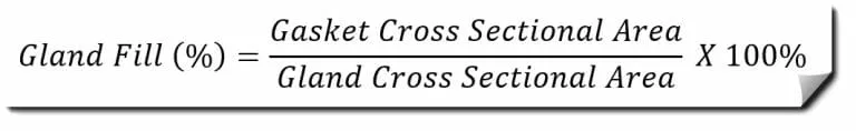
Next, we examined the gland fill percentage of the existing design. Nominally, this 0.9mm X 1.4mm gland and 1.2mm diameter gasket give a gland fill percentage of 90%.
But in real life, parts are never perfect. So, we needed to assign allowed tolerance ranges for the part measurements:
Running the numbers confirmed our suspicions. We needed to reduce the maximum gland fill percentage.
Unfortunately, for a gasket with a round cross-section, our options were limited to some combination of:
Because we were constrained to use the same design envelope, making the gland significantly wider was impossible. Reducing the gasket diameter or increasing the gland depth would cause reduced engagement and possibly compromise the seal if tolerances ran on the small side.
Clearly, we needed to change from a circular cross-section to a design that allows more margin in the axial (gland depth) direction. Critical to its success, it would need to work without taking up more space in the radial (groove width) direction.
We were also concerned about the pull-out strength of the screw features holding the enclosure parts together. We wanted a design to deliver as much compression as possible for a given clamping force.
Clearly, we needed to change from a circular cross-section to a design that allows more margin in the axial (gland depth) direction. Critical to its success, it would need to work without taking up more space in the radial (groove width) direction.
Our solution required further analysis to develop an improved gasket and gland shape to resolve the IPX7 waterproof failures. To achieve this, we regularly conducted a nonlinear finite element analysis. FEA enabled us to explore how design decisions impacted the parts' forces, deformation, and stresses.
Nonlinear Finite Element Analysis is ideal for situations like this where there are large deflections and use of hyperelastic materials like silicone rubber that don’t have linear stress-strain properties.
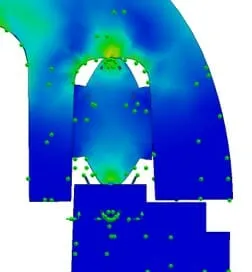
Redesigned Gasket FEA Simulation
After a thorough process of mechanical design review, failure analysis, and material stress simulations, we decided on a hybrid shape (shown below). Our solution was a gasket that was 1.5mm wide (just a little bit wider than the old 1.2mm diameter circular cross-section) and 4.35mm tall (about 3.6 times the height).
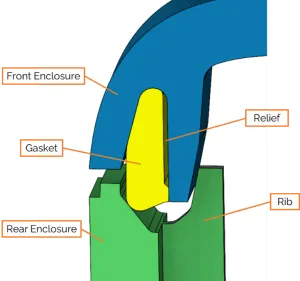
The 50° angle interface between the gasket and rear enclosure creates a hybrid axial-radial seal. Clamping the case screws directly creates one part of the compression force (axial). Then, the case part assembly creates another compression force (radial).
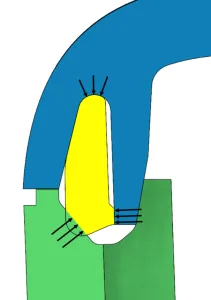
Adding the relief points allowed the material to deflect into the relief area when compressing the gasket. The relief points kept the required clamping force low. Additionally, they created a focused contact area for the remaining material to press against in the rear case groove.
We calculated the new gland fill percentage for the redesigned gasket seal and found that the worst-case gland fill was 95%.
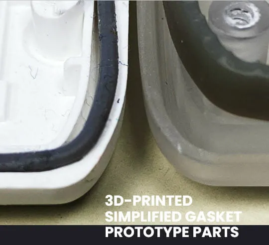
Next, we needed to test parts that would achieve the IPX7 waterproofing specification. We prototyped the redesigned gasket using stereolithography case parts and gasket seals using Carbon DLSTM 3D printing.
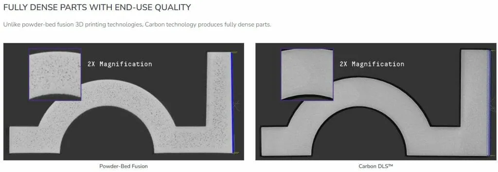
We used testable 3D-printed parts to confirm our redesign solution. Even though end-use quality parts are not as good as production parts, they passed enough submersion tests to give us the confidence to proceed with production tooling. Ultimately, to everyone's satisfaction, the redesign successfully passed our client's IPX7 waterproofing requirement.
The solution to this design challenge required a comprehensive mechanical design review of the materials.
We gained insights into design profiles and performed rapid prototyping to produce testable parts.
Our team also conducted a Finite Element Analysis to build accurate linear and nonlinear material simulations to vet design solutions.
Are you seeing failures with your launched product and in need of a knowledgeable engineering partner to help with analysis and testing to identify the root cause?
Or perhaps you’re ready for a significant design improvement that will take your product’s performance to the next level?
Product innovators turn to AC for end-to-end product development and individual design challenges.
AC engineers help you:
What challenges are holding you back? Let’s talk.