
Throughout this series on GD&T, we’ve explored the importance of communicating our design intent and building a better datum coordinate system that works with the inspector’s tools and techniques. Aaron Nelson, our expert presenter on GD&T, calls this approach “Design for Inspection” (DFI) because we’re using GD&T to drive successful inspection outcomes.
Now let’s take a look at some of Aaron’s most recommended advanced GD&T techniques. These insights are based on his 25+ years of experience using GD&T to develop tighter controls, cleaner drawings, quicker datum construction, and clearer communication.

“I’ve found that I don’t need a lot of tools to be successful with GD&T, but there are several recommendations that I frequently find useful when designing complicated parts. Some of these recommendations simply clarify a few common misconceptions; others are a handful of advanced techniques that are essential to understand and incorporate into our GD&T discipline so we can be efficient and clear about our design intent. Taken together, I hope this series helps you understand how to use GD&T to greater effect, and ultimately helps ensure your success in manufacturing and inspecting parts.”
For complex parts, we can create an orthogonal coordinate system based off of the datums by using basic dimensions.
A helpful illustration of this is found in Dimensioning and Tolerancing, ASME Y14.5-2009, on page 52. It shows how to build an XYZ coordinate system for a non-orthogonal part based off of datums ABC.
Once we define the XYZ coordinate system based on datums ABC, we can use this same methodology to create other views and transformations. For example, we might want to rotate a coordinate system to show the draft direction or some other consideration.
With complex parts, more than one component often interacts with the part. The designer can choose to create multiple coordinate systems based on datum surfaces that interact with each component.
By adding a local datums and coordinate system, we reduce the tolerance between features since only the features that interact with a component are related to a single coordinate system.
Local coordinates systems clarify our design intent for specific part features by:
When working with plastic parts, position tolerances increase as the distance between the features increases. By defining a local region, we can have much tighter tolerances if all our features are close together and measured only to each other.
Insight: Local coordinate systems help reduce tolerances because the distance from the feature to its datum origin will be shorter.
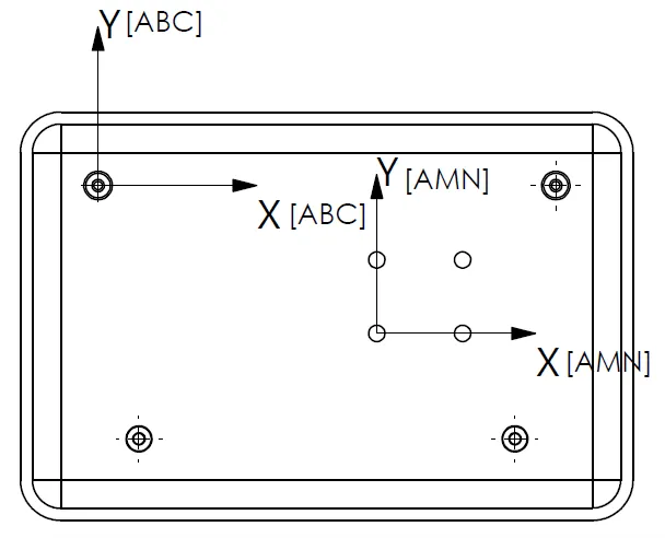
Let’s take a look at an example of when to use a local coordinate system. In this drawing (Fig. 4A), there are four screw holes near the center of the part that don’t interface with any of the other features.
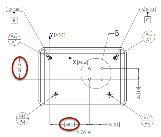
We can create a local coordinate system just for the four holes. And since the distance between the holes is less than the distance between the holes and datums A, B, and C, the tolerances can be less.
Also, in this case, the screw bosses and holes are defined by the draft direction, which is also conveniently the Datum A direction for this part.
For the local datums (Fig. 4B), we define M and N from two of the holes similar to how we established Datums B and C. Only two basic dimensions tie Datum M to the original coordinate system [ABC].
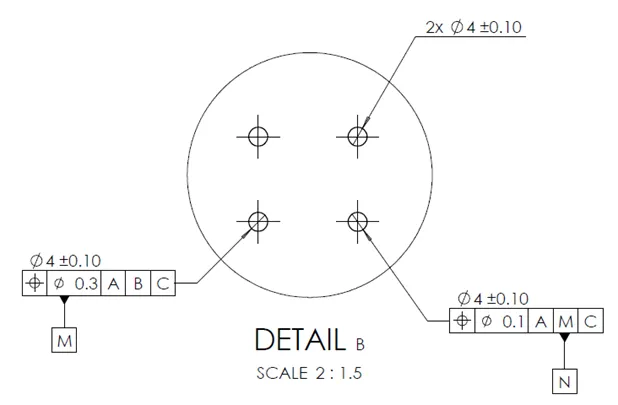
This gives a little bit of control on the position of this local hole pattern, but the designer could choose to not include the two basic dimensions which would create a completely independent coordinate system. The location of the hole pattern would then be determined by notes or block tolerances.
It’s that easy – M and N are now used to create a local coordinate system [AMN].
The other two screw bosses shown in Fig. 4C, that are not datums, can be measured using the basic dimensions with respect to M and N.
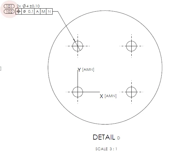
Engineers often try to finish a drawing as quickly as possible and, in doing so, can overlook similar features and the number of inspections required. Let’s look at an example of this.
The designer might be tempted to put the highlighted numbers on the drawing in Fig. 4D.
Let’s improve the drawing by ensuring there are two dimension numbers for the diameter and two for the position, as shown in Fig. 4E.
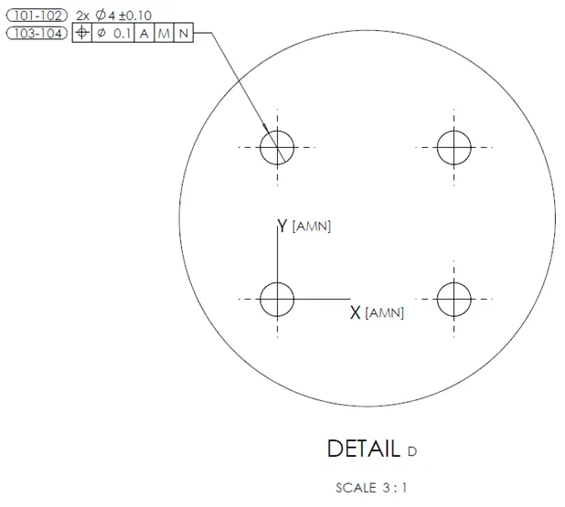
TIP: If there are high multiples of the repeated feature, save space by using a range for dimension numbers.
But wait; what happens if dim 102 is out of spec? Which hole is it? Is it the left one or the right one? It’s clear that we need one more improvement.
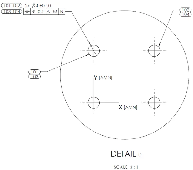
One solution might be to repeat the diameter and position callouts on the right hole, but that creates a chance of typing in the wrong positional tolerance or making it more time-consuming if the tolerance needs to change. Consider if there were 100 holes!
This example in Fig. 4F enables us to be precise with a minimum of repeated dimensions – it also happens to be the fastest to implement.
This convention clearly shows which dimension identification numbers are related to which features and doesn’t repeat dimensions and tolerances.
The most commonly used GD&T callouts are profile and position. Sometimes we use flatness to control orientation and form; less often we call out perpendicularity.
In general, for profile and position, we want to measure the features with respect to our coordinate system.
Our basic dimensions come from the original coordinate system [ABC], as shown in our example using Datums AMN (Fig. 4G).
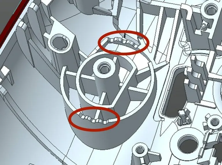
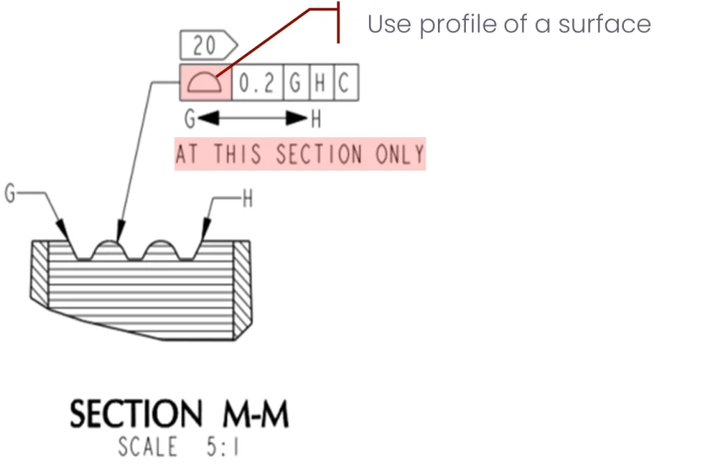
What about complex features, like these detents? (Fig. 4H) How do we control them using a local coordinate system?
We need to control these peaks and valleys using a local coordinate system since the features are generally unrelated to other features in the part.
The profile of those surfaces is important because the surfaces need to be in the right position for the detent to function properly.
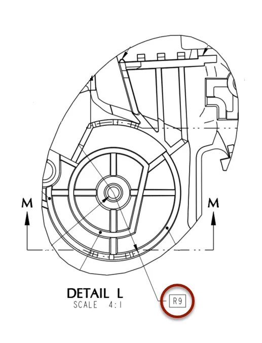
In this drawing, we use a basic dimension, a 9mm radius, that defines a cutting plane to create section M-M. (Fig. 4I)
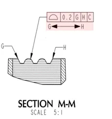
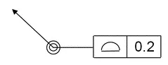
This tolerance reference frame (Fig. 4J) indicates that the profile should be controlled within the 0.2mm tolerance zone using this local coordinate system from points G to H.
How many line elements are there from G to H for these detents? Each line element would need multiple dimensions to locate it properly to the local coordinate system [GHC]. There are eleven (11) line elements between G and H, which means we need dozens of dimensions to control the position of all these features. That’s a lot. But there’s a way around all of this.
Because all CMMs can import CAD geometry, we simply drop in a note on the first page: “USE 3D CAD GEOMETRY FOR BASIC DIMENSIONS.” (Fig. 4K)
From the note, the inspector can simply pull the dimensions from the CAD file – the designer does not need to dimension all these line elements which keeps the drawing uncluttered.

Additionally, by using the convention “G<—->H”, the inspector will report the profile as if it was a single feature.
If that’s not clear, use the continuous feature symbol (Fig. 4L). The value reported would be the maximum deviation of any of the eleven (11) line elements.

The most used GD&T symbol is Profile of a Surface, but it is often confused with Profile of a line which is the same symbol without the line on the bottom. (Fig. 4M)
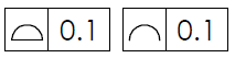
In reality, we rarely need to use Profile of a Line, so let’s focus on the best way to handle Profile of a Surface.
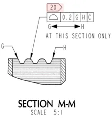
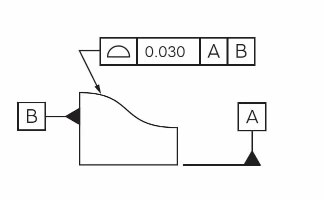
In the example shown in Fig. 4N, we don’t want to measure the whole surface, because it would require the CMM to go in and out of the page multiple times and build up a point cloud of this surface.
Instead, let’s trust our tooling and just say: “AT THIS SECTION ONLY”. This note with a basic radius dimension makes it clear to the inspector what is required.
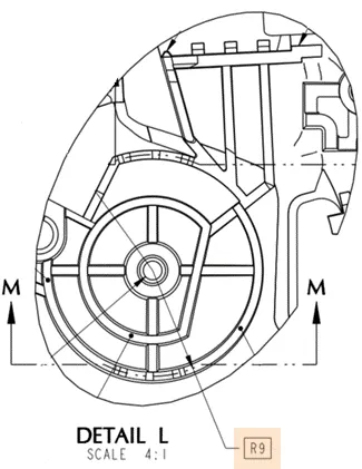
In our detent drawing (Fig. 4O), R9 indicates to the inspector where they should measure the profile of the surface.
Because it’s not practical to get more than one hit on this rib, measuring one cross-section is good enough to confirm it’s within the tolerance specification.
When we know a feature is small and the inspector is going to use a CMM, we can anticipate there’s very little room to take multiple points. Using this approach, we are considerate of the inspector by ensuring the profile is measured at the position called out in the drawing, which helps create a successful inspection.
TIP: Clarify the profile at a specific position to avoid the default of taking multiple points.
The Profile symbol (Fig. 4P) is one of the most commonly used in GD&T. In reality, however, it’s not always clear how profile is measured and reported.
There are two ways to report profile:
For example, in the U.S., nearly all drawings include a note that states: “This drawing is controlled by ASME 14.5-YYYY.”
What is frequently misunderstood is that for Southeast Asian suppliers, most CMM software defaults to ISO reporting of profiles. So, even though we may have called out ASME on the drawing, they report profiles using the ISO method nine times out of ten.
What are the differences, and how is profile measured and reported using both methods?
NOTE: Negative deviations are into the part; positive deviations are away from the part.
Ideally, we want two numbers reported: maximum negative and maximum positive deviation. Actually, for both ISO and ASME methods, that’s really the information we want, though that’s never the information we get. The key takeaway is to remember that most vendors are reporting profile using the ISO method, which is the maximum deviation multiplied by two.
TIP: Ask the inspector to report surface deviations in addition to the standard profile results. This allows you to see which of the two methods they’re using.
Many parts fall into the category of “organic” shapes, meaning they don’t have many or any planar features on which to create a coordinate system. Considering the role that Industrial Design plays in the design of modern consumer electronics, we often have products that are very organic and sweeping. This can mean that for mechanical design, we don’t have many planar features available to build datums on.
For organic-shaped parts, we may need to resort to using non-planar surfaces for datums. However, there will be some issues to anticipate because the position of where we measure a non-planar surface is important. As we reviewed earlier, any deviation in position will change the Z position.
When using non-planar surfaces, we can use a method of datum creation called “bootstrap” – or iterative.
Bootstrap is an iterative inspection method best suited for parts held in a fixture but not necessarily restrained. The inspection involves creating an initial coordinate system with the fixture and also importing it into the CMM. Then, the non-planar surfaces are used to construct a second coordinate system, and the distance between those two origins is measured.
To illustrate the challenge, let’s consider how to create a datum coordinate system to define the measurement of an egg.

When a datum coordinate system isn’t required for an organic shape, use Profile All Over, as shown in Fig. 4Q. This notation indicates taking a cloud of points on the surface, comparing it to CAD, and outputting the deviation.
Note: There are no datums in the reference frame, thus no need for a coordinate system.
For example, when we’re defining an organic silicone part, it would be excessive to create a datum coordinate system, and it wouldn’t be accurate since the CMM probe force would deform the part and cause incorrect measurements. We can specify Profile All Over if we just need to confirm the shape and size.
Then there is a hybrid method that uses All Over to create an unspecified coordinate system, but that’s a topic for another blog.
As we come to the end of this series on GD&T, there is one insight that can save hours of frustration and wasted time. It’s not always possible to convey everything we need to say using GD&T symbols. This means, in some cases, we simply have to use words instead.
To understand why this is important, let’s return to one of the first guidelines we explored in Part 1 of this series: GD&T is a language. So, let’s give ourselves permission to simply switch to a different language.
Remember our overarching goal using GD&T is to be understood. Clarity might mean we combine our specifications and GD&T symbols with some written instructions.
We don’t have to stick to a rigid approach using only symbols because, frankly, there are times we simply need to write it out to be clear and understood.
TIP: Remember, GD&T is a language – the goal is to be understood.
Let's look at a couple of ways we can write inspection instructions without cluttering up a drawing.
Keep in mind, if we struggle to say something, we should expect the reader will also struggle to understand us.
The key takeaway here is that sometimes we need to make it easier on ourselves and the inspector by creating a drawing note and explaining, in words, what is to be measured.
Clearer communication and cleaner drawings are crucial for success with CMs. How can we help ensure the success of your part designs and inspections?